Affichage des articles dont le libellé est mikroc. Afficher tous les articles

vendredi 6 juillet 2012

Talking to an external EEPROM via I2C protocol

Hello,
you may want sometimes to save data that are too much to handle by your poor little pic, well you may thought of using an external eeprom to save all your data their,
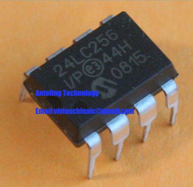
In this tutoriel, I'm going to tell how to interface the 24LC256 eeprom with a 16F887 pic microcontroller.
I2C is a protocol that can allow multiple slaves and multiple masters to be connected in the same network, and that's pretty awsom ^^, most of the time there is only one master and many slaves, but in our case there will be one master (our PIC 16F887) and one slave our (24LC256 eeprom).
The master can communicate with only one slave at a time so how can he make a difference between his slaves?
well that's easy every slave has its unique address in the network for example our 24LC256 address has a 7 bit address that's equal to in binary 0B1010A1A2A3,
A master in a I2C network can read xor write it can't do both of them at the same time, so you may wonder how the slave would know if the master need to right or read from it,
well that's simple if the master want to write in the eeprom it sends 0XA0 and if it want to read it sends 0XA1, in other terms the LSB is the bit responsible for reading or writing.

wiring The 24LC256 EEPROM

A1 A2 and A3 are wired to the ground so our eeprom address is 0B1010000
Wp it's a bit for writing protection or read only, I'm not sur just wired to the ground.
SDA is the pin responsible for sending and receiving data,
SCK is the serial clock
We must use 2 pull up resistor for SDA and SCL (in proteus isis use the pull up resistor model)

Writing and reading from the EEPROM

we will store a data in a specific address then we are going to read data from that address.
unsigned char i = 0;
char txt[4];
void rc(){
     uart1_write(10);
     uarT1_write(13);
}
void main(){
  uart1_init(9600);
  I2C1_Init(100000);
  uart1_write_text("initialize I2C communication");rc();
  I2C1_Start();
  uart1_write_text("Start I2C communication");rc();
  I2C1_Wr(0xA0);
  delay_ms(10);
  uart1_write_text("write eeprom address");rc();
  I2C1_Wr(0x00);
  delay_ms(10);
  uart1_write_text("write low address");rc();
  I2C1_Wr(0x00);
   delay_ms(10);
   uart1_write_text("write high address");rc();
  I2C1_Wr(26); //donnée à écrire
  delay_ms(10);
  uart1_write_text("send to be stored");rc();
  I2C1_Stop();
  uart1_write_text("Stop I2C communication");rc();
  Delay_100ms();
  I2C1_Start();
  uart1_write_text("Start I2C communication");rc();
  I2C1_Wr(0xA0);
    delay_ms(10);
    uart1_write_text("write eeprom address");rc();
  I2C1_Wr(0x00);
     delay_ms(10);
     uart1_write_text("Start I2C communication");rc();
  I2C1_Wr(0X00);
  delay_ms(10);
  uart1_write_text("write low address");rc();
  I2C1_Repeated_Start();
  uart1_write_text("write high address");rc();
  I2C1_Wr(0xA1);
  delay_ms(10);
  uart1_write_text("read eeprom address");rc();
  i=I2C1_Rd(0);
  uart1_write_text("read stored data");rc();
  I2C1_Stop();
  uart1_write_text("Stop I2C communication");rc();
  bytetostr(i,txt);
  uart1_write_text(txt);rc();
}

I hope that was clear, don't stop sharing!!


dimanche 6 mai 2012

USB communication


In this tutorial I'm using a PIC18F4550 with 48MHz crystal to communicate through usb with PC.
If you are using proteus ISIS I'm happy to tell you that there's a wonderful feature which create a virtual usb driver so you don't need any electronics to test your program.

I'm going to show you how to create a project that includes the usb HID (Human interface devices) library. So after this project you will be able to create your own HID devices with your product and vendor IDs.

First start by creating a new Projects with all the settings mentioned above and copy this code which is by the way the example code given by the Help.

unsigned char readbuff[64] absolute 0x500;   // Buffers should be in USB RAM, please consult datasheet
unsigned char writebuff[64] absolute 0x540;

char cnt;
char kk;

void interrupt(){
   USB_Interrupt_Proc();                   // USB servicing is done inside the interrupt
}

void main(void){
  ADCON1 |= 0x0F;                         // Configure all ports with analog function as digital
  CMCON  |= 7;                            // Disable comparators

  HID_Enable(&readbuff,&writebuff);       // Enable HID communication

  while(1){
    while(!HID_Read())
      ;

    for(cnt=0;cnt<64;cnt++)
      writebuff[cnt]=readbuff[cnt];

    while(!HID_Write(&writebuff,64))
      ;
  }
}
The code simply send back what he received ^^

Now Tools->HID terminal

Set your VID and PID your Vendor Name and Product Name as you want.
Then select the mikroC radio and save your descriptor file with your project files (not an obligation but recommended :p ).

Go to view-->project manager
right click on the "source" folder and choose "add files to project" to add the descriptor file you already created.

before compiling one last step:
go to edit project and set it like in the picture


Finally Compile your project. It should work fine if you are not using the demo version.


lundi 27 février 2012

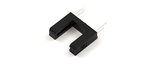
Read data from an optical fork or an encoder

PIC has a lot of interesting features and one of them is the amazing portb that can create hardware interruption in each variation.

the code above I used to read data from an optical fork.

The code is very simple:

every time there is a state change in one of the portb pin we enter the interrupt routine and we can do whatever we want to do there.

I used the timer 0 interruption just in case you want to do know the number of hardware interruption each period of time.

I used PIC18F4550 and 40Mhz oscillator.

int read=0;
int left=0;
int right=0;
int l =0;
int riL =0;
char txt[7];
void interrupt(){
if(TMR2IF_bit){
portd.RD4=~portd.RD4;
left=l;
l=0;
TMR2IF_bit=0;//never forget to put 0 int the flag after interruption
}
if(INTCON.RBIF==1){
portd.RD2=~portd.RD2;
l++;
read=portb;
INTCON.RBIF=0;
}
}
void init(){
portd=0X00;
trisd=0X00;
portb=0X00;
trisb=0XFF;
//initialisation de ports
intcon=0XC8;
//initialisation des interruption global(GIE,PIE,RBE)
t2con=0X07;
TMR2IE_bit=1;
//timer 2
uart1_init(9600);
}
void main() {
init();
while(1){
inttostr(left,txt);
uart1_write_text(txt);
uart1_write(10);
uart1_write(13);//pour la visualisation

};


}

mercredi 25 janvier 2012

UART and RS232 communication

Hello,
today I'm going to show you how to communicate through uart with the RS232 protocol.
how to send and extract data.
let's start with the sending.
with Mikroc you can send to types of data (character and text).
A character can have a value from 0 to 255 but a text is a string of characters.
To do so we need to call the "UART library" from Mikroc

This program sends a character (or a number less then 256) if a request was demanded;

unsigned char read=0
Void main(){
     uart1_init(9600);
while(1){
   if (uart1_data_ready()==1){
       read=uart1_read();
      uart1_write(read);
 }
}
}

this program read a string of characters then resend this string
char txt[120];
void main(){
   uart1_init(9600);
while(1){
    uart1_read_text(txt,"#" ,255);
uart1_write(10);
uart1_write(13);
uart1_write_text(txt);
}
}

What about the electronics:

The UART protocol is amazing but we can't communicate with a PC using it so we have to convert this protocol to an other one that is adopted by PC, the great one is the famous RS232 protocol.
RS232 is very close to the UART protocol the only difference is the logic level:
RS232: 1-->+12V 0-->-12V
UART: 1-->5V 0-->0V
So all we have to do is to find a way to convert the logic level from PC to PIC and From PIC to PC
The best solution is the one provided by Maxim the MAX232 circuit:
This little circuit does the job quite well.
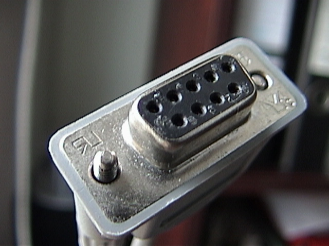
The RS232 protocol use the DB9 port on PC but we can't find this port a new PCs that's why we need a converter from the RS232 to USB we use (just like its function) a converter cable from RS232 to USB just like this one:

Some cables requires a driver to be installed so you need to find the right one.
Linking....
The best circuit that I personally tried it is this one and it works amazingly:
 

samedi 24 décembre 2011

LBOTTI suiveur de ligne

Donc voilà lbotti un robot suiveur de ligne il n'est pas très rapide, d'ailleurs son nom indique ça bien mais en revanche il est très stable.
Il n'est pas très joli aussi :))
J'ai crée ce robot dans le but pour participé à la 2ème édition de robocomp avec le Team MAZON http://robocomp.ieee-enis.org/?page_id=216 et j'ai pu à travers lbotti d'apporter la 5ème place avec un temps environ de 34sec.
Schéma synoptique

Tableau de capteurs de lumières
Le tableau de capteurs est composé de 9 led rouges émettrices et 8 photorésistances.
J'ai choisi le couleur rouge car il est le plus adapté pour les circuit dont le contraste est faible (exemple ligne bleu sur fond rouge) et bien sure ce qui marche pour un contraste faible marche encore mieux avec un contraste fort, qui est le cas pour la compétition.
J'ai choisi les Ldr car ils sont disponibles dans le marché tunisien.

Comparateurs:


J'ai utilisé des comparateurs pour deux raisons:
-pour s'adapter aux variations de la lumière ambiante en changeant la valeur de la tension Vref de comparateurs
-pour minimiser le temps de traitement et donc le temps de réponse. puisque les variables numériques sont interpréter plus rapidement que les variables analogique.
Les comparateurs sont des LM324

Microcontrolleur:
 PIC 16F877:
code:
unsigned char lastturn=3;
void init(){
     pwm1_init(20000);
     pwm2_init(20000);
     pwm1_start();
     pwm2_start();
     pwm1_set_duty(0);
     pwm2_set_duty(0);
     portd=0X00;
     trisd=0XFF;
}
void setPWM(unsigned char r,unsigned char l){
     pwm1_set_duty(r);
     pwm2_set_duty(l);
}
void rightr(){
     setPWM(0,180);
     while((portd.RD4==1)||(portd.RD5==1));
     setPWM(0,0);
     delay_ms(20);
}
void leftr(){
     setPWM(180,0);
     while((portd.RD3==1)||(portd.RD2==1));
     setPWM(0,0);
     delay_ms(20);
}
void main() {
init();
while(1){
if((portd.RD7==1)&&(portd.RD0==1)){//reglage fine
 if(portd.RD6==0){setPWM(188,112);lastturn=2;}
  if(portd.RD1==0){setPWM(112,188);lastturn=1;}

if(portd.RD5==0){setPWM(175,125);lastturn=2;}
if(portd.RD2==0){setPWM(125,175);lastturn=1;}

if(portd.RD4==0){setPWM(150,150);lastturn=2;}
if(portd.RD3==0){setPWM(150,150);lastturn=1;}
}
else if((portd.RD7==0)&&(portd.RD6==0))leftr();
else if((portd.RD0==0)&&(portd.RD1==0))rightr();
else if((portd.RD7==0)||(portd.RD6==0)||(portd.RD5==0)||(portd.RD4==0)){setPWM(180,0);lastturn=2;}
else if((portd.RD0==0)||(portd.RD1==0)||(portd.RD2==0)||(portd.RD3==0)){setPWM(0,180);lastturn=1;}

else if(portd==0XFF){if (lastturn==1) rightr();
                if(lastturn==2)leftr();
                }
else {
setPWM(250,250);
}
}
}

Interface de puissance:
j'ai utilisé un L293D qui est un double pont en H  qui supporte un ampérage maximal de 1.2A

 Moteurs:
2 micro moteurs DC.
http://www.mechs.fr/product.php?id_product=61

La régulation PID:
Je ne suis pas très sure du code pour le moment mais il sera mis à jours bientôt avec des explication

#define TARGET 50;
unsigned char read=0;
unsigned char Kp=0,Ti=0,Td=0;
int commande=0, error=0, lasterror=0, proportional=0,integrator=0, derivator=0, correction=0;

void init(){
     portd=0X00;
     trisd=0XFF;
     uart1_init(9600);//initialize baude rate
}
void backline(){
     uart1_write(10);
     uart1_write(13);
}
void printMenu(){
uart1_write_text("Welcome to Robot BOTTI :)))");
backline();
uart1_write_text("PID Tuning!");
backline();
uart1_write_text("1: KP proportional");
backline();
uart1_write_text("2: Ti integrator");
backline();
uart1_write_text("3: Td Derivator");
backline();
uart1_write_text("4: vitesse maximal");
backline();
uart1_write_text("5: Go BOTTI");
backline();
uart1_write_text("Your choice");
}
void setPIDvalues(){
 printMenu();
 while(!uart1_data_ready());
 read=uart1_read();
 uart1_write(read);
switch(read){
              case '1':
              backline();
              uart1_write_text("Kp= ");
              while(!uart1_data_ready());
              Kp=uart1_read();
              uart1_write(Kp);
              break;
             
              case '2':
              backline();
              uart1_write_text("Ti= ");
              while(!uart1_data_ready());
              Ti=uart1_read();
              uart1_write(Ti);
              break;
             
              case '3':
              backline();
              uart1_write_text("Td= ");
              while(!uart1_data_ready());
              Td=uart1_read();
              uart1_write(Td);
              break;
             
              case '4':
              backline();
              uart1_write_text("commande= ");
              while(!uart1_data_ready());
              commande=uart1_read();
              uart1_write(commande);
              break;
             
              case '5':
              backline();
              uart1_write_text("Good luck");
              break;


 }
}
unsigned char sensVAl(){

      if(portd==0B11100111)return 50;
      if(portd==0b11001111)return 58;
      if(portd==0B11011111)return 64;
      if(portd==0B10011111)return 72;
      if(portd==0B10111111)return 80;
      if(portd==0B00111111)return 92;
      if(portd==0B01111111)return 100;
      if(portd==0b11110011)return 42;
      if(portd==0b11111011)return 36;

}
unsigned char start(){
unsigned char sensorValue;
sensorValue=sensVal();
error=sensorValue - TARGET;
integrator=error+lasterror;
if(integrator>=2)integrator=0;//en cas de stauration
derivator=(error-lasterror)/2;
correction=kp*error+Ti*integrator+Td*derivator;
pwm1_set_duty(commande+correction);
pwm2_set_duty(commande-correction);

}
void main() {
     init();
     setPIDvalues();
     while(!portb.RB0);
     while(1){
     start();
     }

}


mercredi 21 décembre 2011

Le servomoteur modifié


Comprendre le fonctionnement d'un servo modifié!

Pour comprendre le fonctionnement d'un servomoteur modifié (hacked) il faut d'abord comprendre le fonctionnement interne d"un servomoteur normal.
Le servomoteur normal nous donne une position selon notre commande qui varie entre 1ms et 2ms.
Donc le servo calcul l'écart entre sa position actuelle et sa position désirée tout le 20ms si l'écart est nul le servo maintient sa position sinon il tourne jusqu'à l'écart soit nul de nouveau.
La vitesse de servo entre 2 position n'est jamais constante, elle est relative à l'écart calculé à chaque fois.
Par exemple:
Pour passer de 90° à 0° le servo commence à tourner d'une grande vitesse, vue que l'écart est grand puis il diminue jusqu'à qu'il arrive à la position 0°.
Mais comment un servo peut connaître sa position?
En fait l'arbre de moteur de servo est attaché à un potentiomètre la valeur de sortie de ce potentiomètre est relative à sa position.
Supposons qu’on a enlevé se potentiomètre, le servo ne sait plus sa position réel. On peut même lui donné une fausse information de sa position en insérant à la place de potentiomètre un pont diviseur qui est en fin de compte un potentiomètre à valeur fixe.
Supposons encore que le pont diviseur est constitué de deux résistances égales. Le servo va croire qu’il est toujours au milieu.
Donc si la commande est de 1.5ms (commande pour que le servo normal tourne jusqu’à atteindre le milieu) le servo ne tourne pas puisque l’écart est nul.
Si la commande est de 2ms l’écart est donc maximal le servo commence à tourner avec sa vitesse maximal et qui reste maximal puisque l’écart est toujours fixe.
Si la commande est de 1ms l’écart est donc maximal mais négatif le servo commence à tourner avec sa vitesse maximal dans le sens contraire et qui reste maximal.

Les étapes pour modifier un servomoteur:

voilà un vidéo qui explique comment modifié un servo par roboticsed:


Pourquoi tous ces trucs, il est plus facile d’acheter un moteur DC et le commander en PWM!!

Oui c'est vrai, mais le servomoteur présente autre avantages plus que sa commande facile.
         Il n'est pas très cher par rapport au couple qu'il présente.
         Il est disponible par tout
         Il n'exige pas une interface de puissance
Code C:
int cnt=0;
unsigned char down=0;

void interrupt(){
if(TMR2IF_bit){ //la résolution de timer est ~= 55µs
     cnt++;
     if(cnt==down) portb=0;// la valeur angle varie entre 0-->180
                                        //cnt= 18 se traduit par 1ms
                                        //cnt=27 se traduit par 1.5ms d'ou 90°
     if(cnt==370) {portb=1;cnt=0;}
     TMR2IF_bit=0;//l3alam yarja3 lelsfer
     TMR2=0;
     }
}

void main() {
portb=0X00;
trisb=0X00;
T2CON=0X04;
TMR2IF_bit=0;
TMR2=0;
TMR2IE_bit=1;
INTCON=0XC0;
while(1){

down=27;//moteur en arret
delay_ms(1000);
down=36;//moteur en avance vitesse maximal
delay_ms(1000);
down=18;//moteur en recul vitesse maximal
delay_ms(1000);
}
}

A bientôt :)